TL;DR: The local rec center was short on helping hands for my soldering classes, so I designed an all-in-one PCB holder!
Have you ever tried to solder without a helping hand? It’s one of these tools you don’t always think of when you are shopping for your first soldering corner. They don’t have to be very expensive, but when you’re trying to outfit a whole classroom for soldering, it adds up! Which is why I only had five helping hands for the ten students taking my Intro to Soldering class at the rec center last week. So until we can buy enough for everyone…3D printing to the rescue!
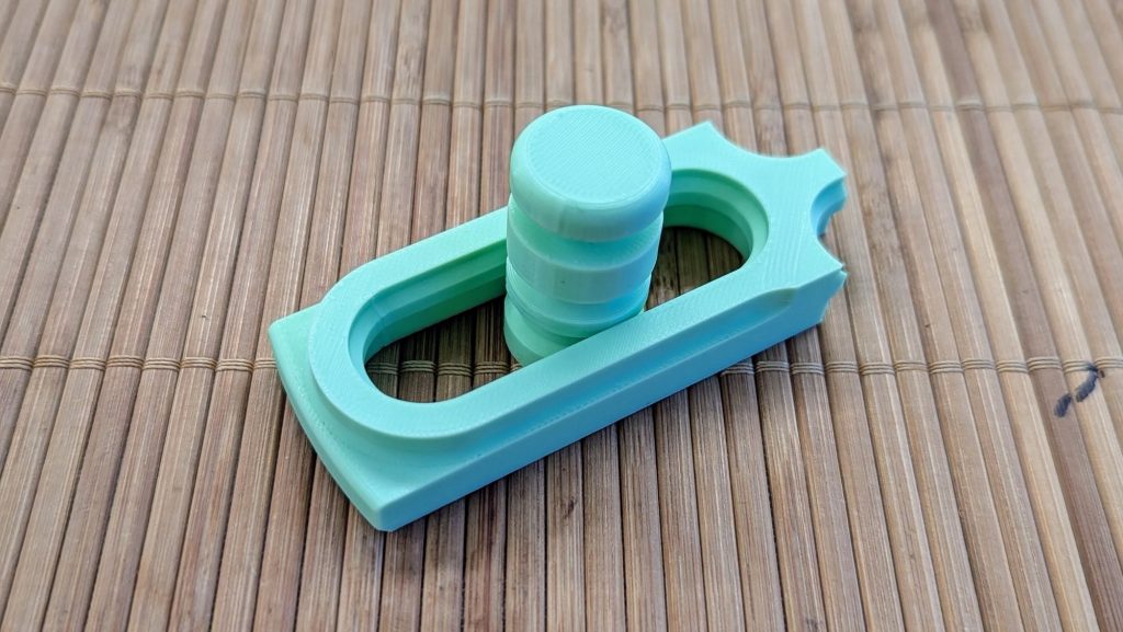
From print-in-place attempts…
I have been learning more about joints and print-in-place designs in Fusion 360 designs recently. This seemed like a good time to put it all to work in an actually useful design! I started with a big rough print-in-place slider to see what kind of tolerances I could get away with. It worked great and had a nice slider movement, even if it was wiggly in every possible direction! But it was a good first step, and it proved that my A1 Mini could at least pull that much off.
For the next step, I focused on making the slider design smaller while still working. There was a chance the smaller part would fuse with the track, but it still worked out – wiggles and all! Not optimal, but it suggested that maybe changing scale wasn’t having a huge impact on tolerances. Good news!

Next up was adding the post to actually hold up electronics projects and boards, then iron out tolerances. I decided I didn’t have to use the same value for my horizontal and diagonal tolerances. I started a partial print for testing, and it worked out!
I DO THE COMPLICATED STUFF SO YOU DON’T HAVE TO.
Gimme some money.
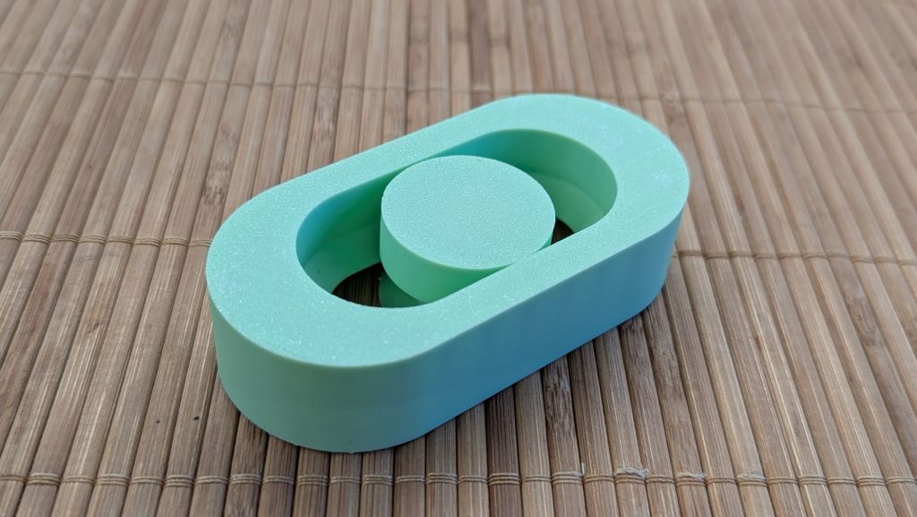
…To print-in-place magic!
With my new tolerance values – 0.2mm for the horizontals and 0.1 for the diagonals, if you’re curious – wiggle was highly reduced on the side-to-side axis and almost non-existent on the up-and-down axis. I had already integrated the longer tracks into a base that would fill as much of the print plate on my A1 Mini as possible.
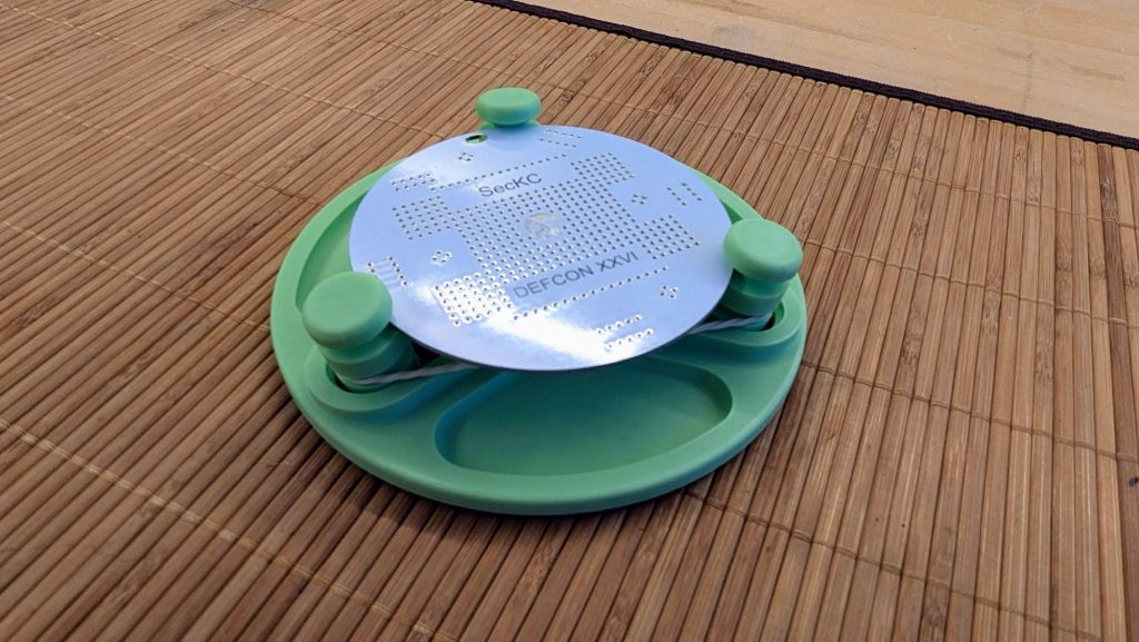
This might look like a big jump between this step and the one before, but we really just multiplied the amount of tracks and posts around a central axis, and added a base. After I also added a few trays between the tracks so we can store components there, then a few cosmetic changes and branding.

Here are the settings I used for my successful prints:
- Filament: Generic PLA, 1.75mm
- Layer height: 0.12mm
- Infill: 15% to 20%, grid or gyroid
- Walls: 2 to 4
- Top/Bottom layers: 2 to 4
- Supports: None
With these settings, the final PCB holder takes about 2h30 minutes and 67 grams of filament at to print on my A1 Mini. Just add a rubber band and start soldering! I was able to hold a Pi Zero (65mm x 30mm) and an even small Bluetooth audio controller without any problems.
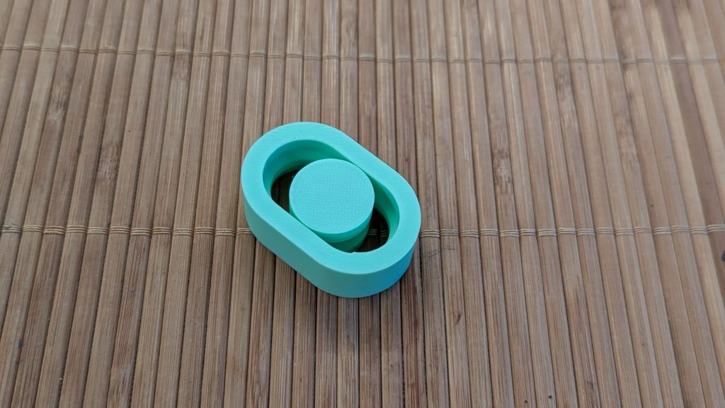
Try before you print!
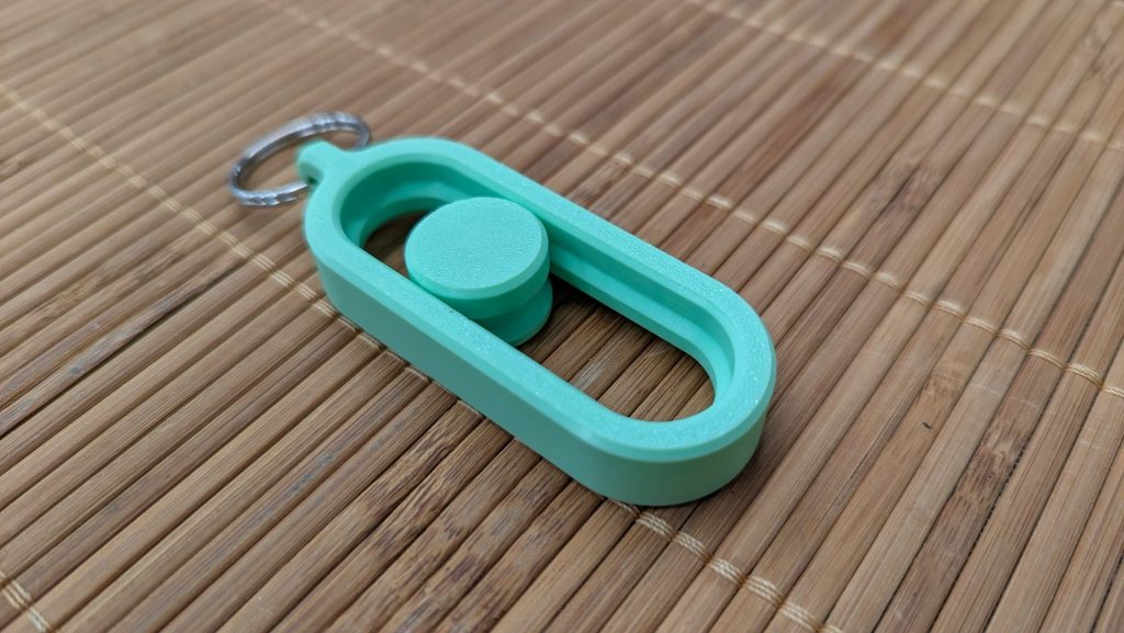
The success of this print relies entirely on being able to print without parts fusing together! I would hate for you to waste time and material on a weird paper weight! So before printing this PCB holder, try this keychain first. I tuned it to the same tolerances as the PCB holder, only takes about 30 minutes to print and 10 grams of filament to print at 0.12mm resolution.
Have you printed the test keychain successfully? Great! Two options:
- Hobbyists can grab the 3D-Printed PCB Holder from Cults, or access all my designs by supporting me on Patreon!
- For anybody else, click this link to talk licensing!
Enjoy!