TL;DR: I pulled all the tips I could find across the Internet to design the best 3D printed fasteners I ever made. What will you do with them?
I recently watched My Dress Up Darling – a really cute show about passionate people doing things they are passionate about (mostly cool cosplay stuff) and started hanging out on the Cosplay Connect Discord server. Around the same time, I started teaching a desktop manufacturing pipeline at the local community college.
The conversations about props making on Cosplay Connect made me wonder: wouldn’t it be cool if you could 3D print something entirely, even on a tiny 3D printer like the A1 Mini? And assemble the 3D printed parts without needing glue or metal fasteners to insert into a part with a soldering iron?
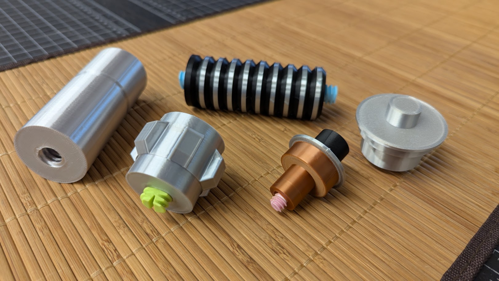
Turns out, yeah, it’s pretty cool! This lightsaber is split in parts that let you print it in the correct color (no AMS necessary). It comes together using 3D printed threads and I’ll publish it soon if I can. Until then, if you want to try and see if your 3D printer can hack it, try the runner sheets I posted on Cults!
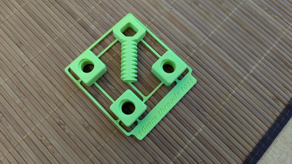
If you’re interested in designing your own threads for your projects, grab a drink and a snack and keep reading. You’re gonna love the first stop on our journey, where we find why 3D printed threads are a terrible idea in the first place.
3D printed threads kinda suck.
If you compare 3D printed threads in bolts or screws with their metal cousins from the local hardware store, it’s not even a challenge. First, 3D printed threads are very fragile compared to metal fasteners due to a combination of materials and manufacturing processes.
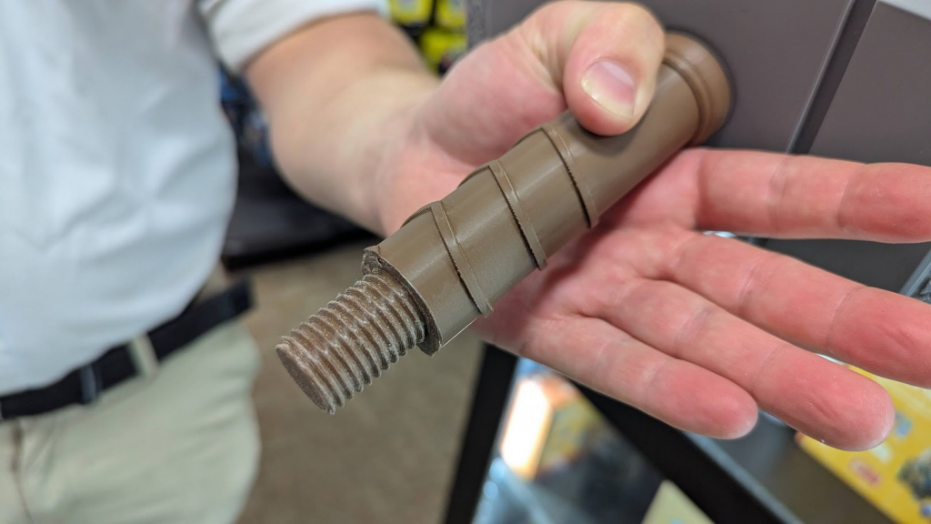
Second, 3D printed threads are hard to use when they work at all: filament printer resolutions and 3D printed plastics are nowhere near the fine threads you can get from industrial manufacturing. That makes 3D printed threads really crunchy and require a lot of force. With all that extra force, if your threads don’t break, they will just get stuck!
Third, 3D printed threads are unreliable to print and need a lot of post processing. They don’t have a lot of surface area to provide adhesion, which means they can pop right off the print bed. As for the threads, they need supports to print properly meaning they need cleanup. An absolute waste of time for something that was supposed to save time!
Here’s the good news: fragility, ease-of-use, print reliability and cleanup problems can be solved or have been solved in different places. We just need to bring all these solutions together! So let’s design and print solid, functional and reliable models for 3D printed threads.
What does the perfect 3D printed thread look like?
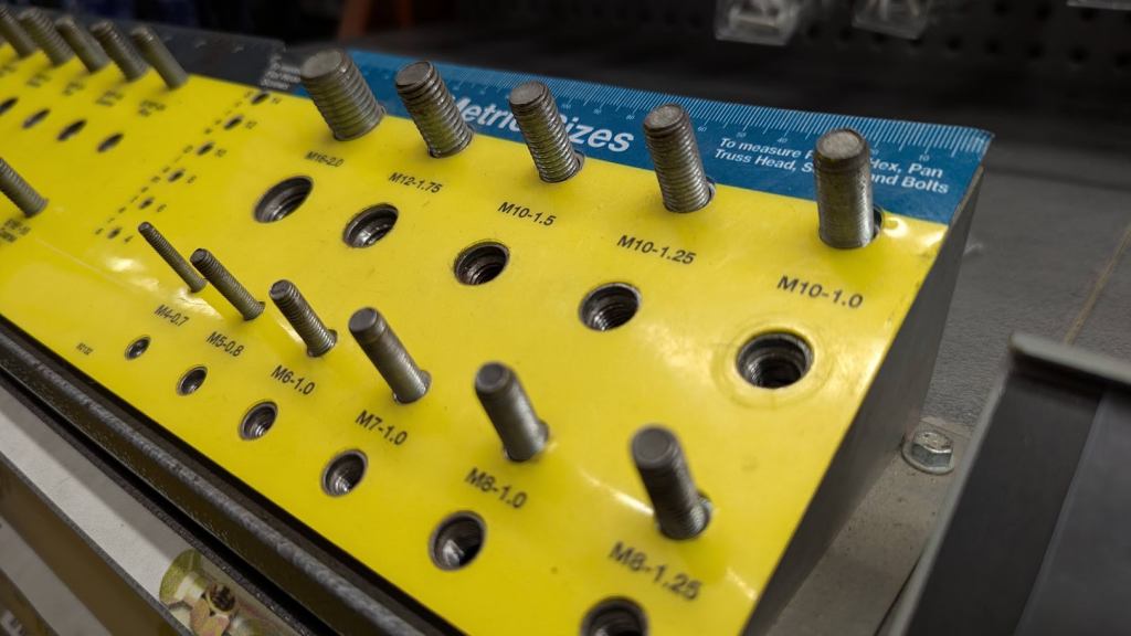
Because we can design things in any size we can, doesn’t mean we have to. For reliability’s sake, I decided to focus on threads in diameters of 10, 12 and 16mm. I picked these three diameters based on the most common Metrics fastener sizes at the local hardware store to focus my design efforts. For our example, we are going to make threads with a 16mm diameter.
Fire up Fusion360 (yes, they do still have a Personal Use license) and create three bodies in three separate components:
- Two cylinders with a 32mm diameter and a height of 30mm, one on top of the other. We will call these Part #1 (at the bottom) and Part #2 (at the top).
- One cylinder with a 16mm diameter and a height of 20mm, centered (horizontally and vertically) between our cylinders. We will call this one Connector.
- Finally, use the Combine tool to cut the Connector from Part #1 and Part #2 (and yes, we’re making sure to Keep Tools): we will call the space left behind the threads well.
Your design should now look like the picture below (I threw in a Section Analysis to better show how everything fits, and turned on Component Colors too).
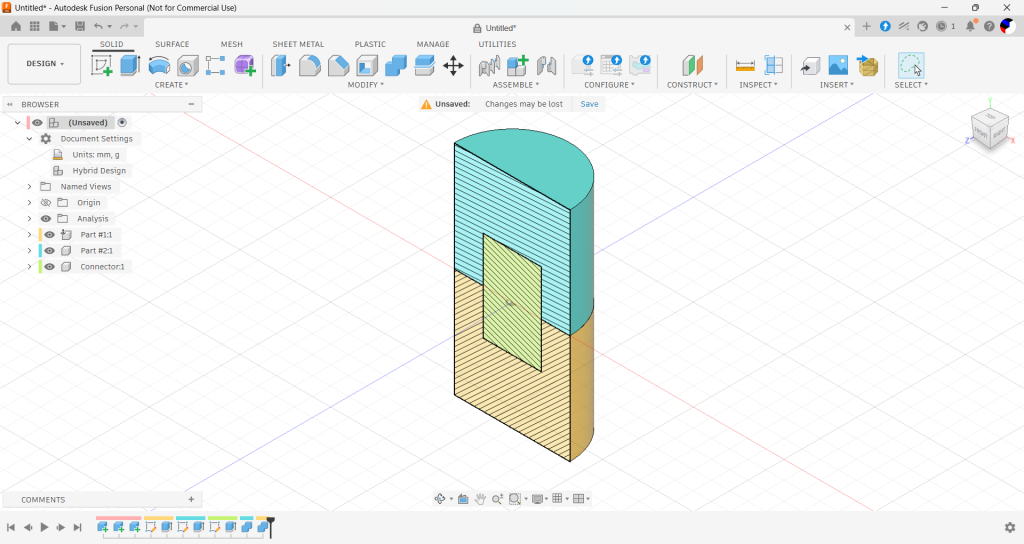
Now let’s make some threads! Fusion makes it easy. Toggle the visibility of Part #1 and Part #2, then select the outside face of the only remaining component, our Connector. And now follow these steps!
- Click on the Create menu to open the Thread tool.
- In the Thread tool, start by checking the Modeled and Full length boxes: this will actually create threads geometry all along the side of your connector instead of making up a visual representation of it.
- In the Thread type dropdown menu, pick the ISO Metric Trapezoidal Threads option. The top (or crest) of this thread profile is flat and easier to print for filament 3D printers.
- Our threads’ Size should be 16mm, but sometimes Fusion changes that value. Ask someone smarter why! If it does, switch the value back to 16mm.
- You can leave the other options alone for now: click the Remember Size checkbox as we will be using the same value all over our model, then OK to generate our threads
At this point, your this is what our Thread menu and our Connector threads should look like with visibility for Part #1 and Part #2 turned off, and the Section Analysis turned off.
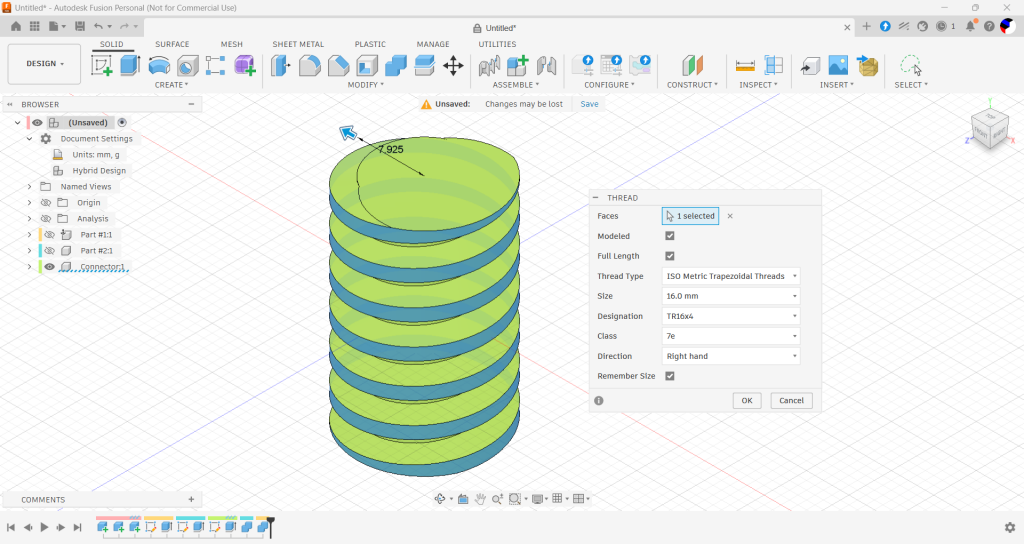
All good? Great! Then let’s make matching threads on Part #1 and Part #2.
Follow the same steps as for our Connector, making sure to use the same Isometric Trapezoidal threads profile and the matching diameter: it’s not unusual for a different diameter to sneakily slip through the cracks! Below is what our design should look like right now with all Components visible and the Section Analysis turned back on to see what we are doing.
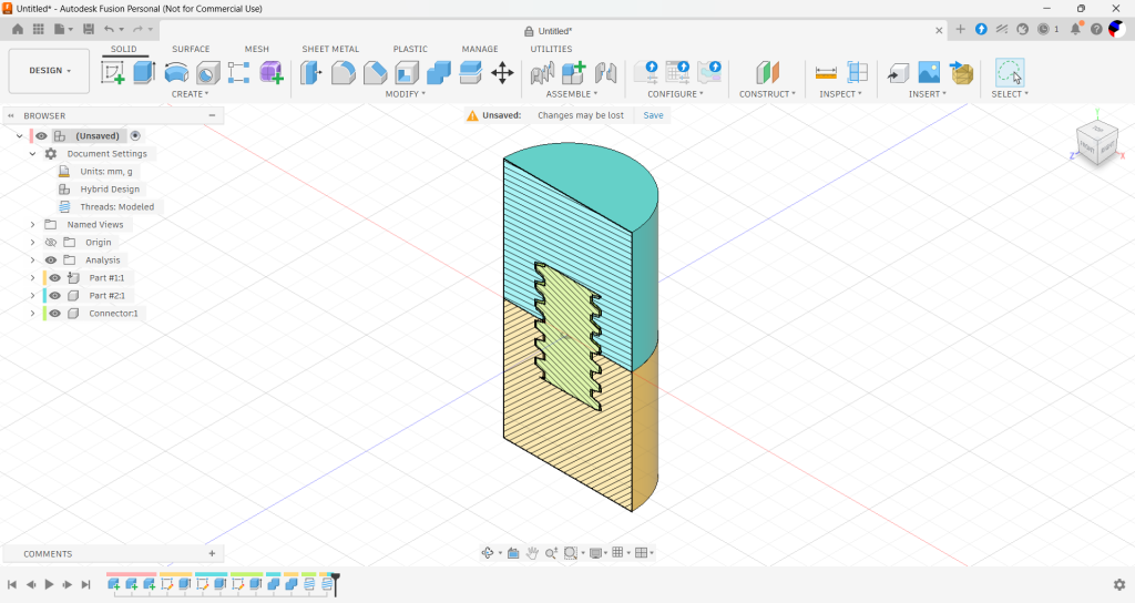
Sometimes, some of the threads on the Connector overlap with some of the threads for Part #1 and Part #2: we will manage this later.
Solving 3D printed threads problems: fragility
So now we have basic modeled threads. Great! This is as far as most online tutorials will take us. Remember all the reasons why 3D printed threads suck I mentioned earlier? Let’s take care of them now!
First up is reliability: print our Connector standing on its flat side vertically and it might break across the layer lines with enough force applied. On top of that, much as I love the last few generations of filament 3D printers, that footprint isn’t much to talk about: it might still pop right off. So let’s make a nice flat surface to work with!
Create an Offset Plane 10mm off the top of thread and start a new sketch there. Let’s trim this Connector up!
- You might be tempted to project the existing Connector Body on our new Sketch. Don’t. Instead…
- Draw a 16mm circle centered to the origin of our design.
- Draw two Construction lines from the center of our circle to its perimeter, one on the X axis, one on the Y axis.
- Finally, draw two rectangles symmetrical to each other across the X and Y Construction lines . Extent the rectangles past the outside perimeter of our 16mm circle. The inside edge of each rectangle (closest to the center of the circle) should be 1/6 of the thread diameter’s away from the perimeter of our circle.
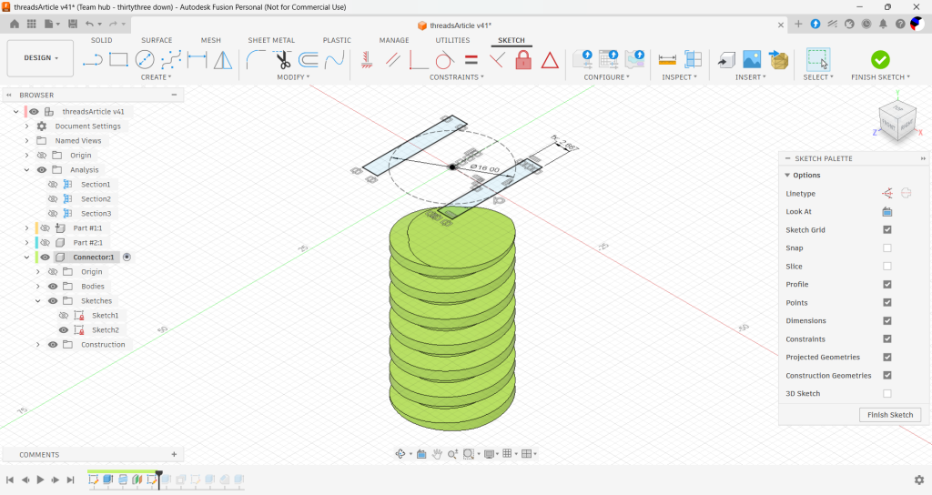
For reference, above is what our Sketch should look like at this point. If that’s where you are, great! Let’s continue. All we need to do is Extrude our two rectangles all the way down to the bottom of the Connector to trim it flat on each side! Have our new extrusion Cut the Connector (Distance: All or To Object should do the trick) and we are good to go.
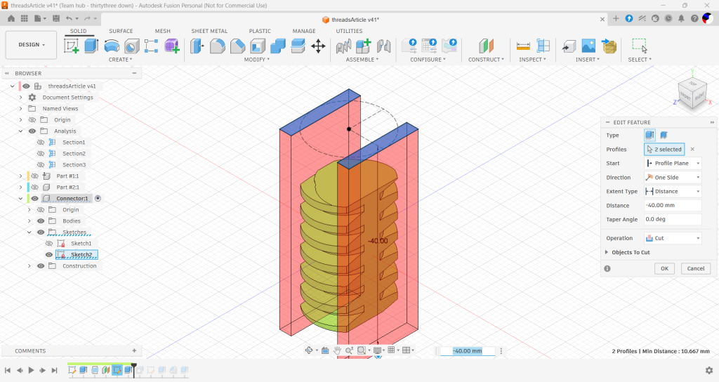
“Good to go?!? We just cut out a third of the diameter of the Connector! How is it going to thread at all?” you might think. As it turns out, as long as our threads have something to bite into – and that’s the threads on Part #1 and Part #2 – that will not be a problem! This long flat side also lets us print threads sideways on our 3D printers: they will stick to the print bed more reliably and any mechanical stress on the thread along the layer line will spread so that the thread will flex before it breaks.
And guess what: we also solved our supports and cleanup problem! Print these threads horizontally and at a good resolution – my favorite is 0.12mm – and you won’t need supports to print them, and then no supports to clean up. Now let’s look at fixing our ease of use and excessive force problem!
Solving 3D printed threads problems: crunchiness
Yeah, sorry, I’m gonna call it crunchiness: that feeling when you’re turning a thread into another, and the tolerances are so tight that you can feel it go krrr (usually just before getting stuck). Let’s decide it’s a technical term and move on!
We already fixed crunchiness a fair bit when we picked an Isometric Trapezoidal Threads profile. Now we just need to give our printers a little more help by factoring in a tolerance 3D printed plastic and how it oozes and settles out of the 3D printer. On our Connector:
- Select all four faces of our threads
- Click on the Offset tool under the Modify tool set
- Put in a negative offset of 0.12mm
- Repeat with the threads on Part #1 and Part #2.
- While we’re here, select the top and bottom of the threads wells for Part #1 and #2 and apply a negative offset of 1mm. That way, our threads will have room at the top and at the bottom and we will never run into a vertical fit issue.
This 0.12 millimeter offset is more than enough to remove any crunchiness on contemporary printers without adding enough wiggle to mess with accuracy and a good fit. Here’s another screenshot with another Section Analysis on to show how things look with our added tolerance for the threads as well as at the top and bottom of the thread well.
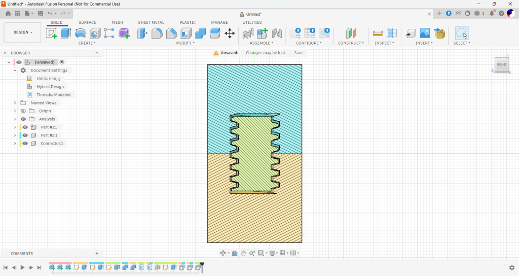
So now we have fixed everything we are done, right? Sure, but why stop there? Now that we made 3D printed threads functional, we can make them even better. We can make them screwdriver-compatible.
Better 3D printed threads: now screwdriver-ready!
So far our threads should print great and work great at 0.12mm resolution on your off-the-shelf consumer 3D printer. If they break, and they shouldn’t since they are printed in the long direction, we can replace them since they are an independent part. Even better: the trim we cut on each side even lets us grab them with a pair of fine needle-nose pliers or tweezers if we need to! But we can go a little bit further and make them screwdriver-friendly, with this next trick!
Create an Offset Plane 10mm off to the left or right of our trimmed surface and start a new sketch there. Let’s add a screwdriver notch!
- This time, we can project the existing Connector Body on our new Sketch. Then…
- Draw a vertical construction line from the Origin point of the Design, all the way up to the top of our projected Connector body.
- Draw a 3 millimeters wide, 5 millimeters deep triangle across our vertical construction line, pointing down. The top two points sit at the top of our projected geometry, and the triangle is symmetrical across our construction line.
If you’re feeling fancy (like me) you can even add a horizontal Construction line across from the Origin center and mirror our triangle so you can use a screwdriver entry on both sides. At this point, here’s what your Sketch should look like right now. If it looks the same, great!
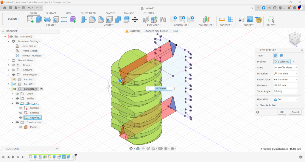
All we have left to do is cut out our threads, and add a 1 millimeter chamfer at the bottom of the notch. You can see below what our connector should look like, and how it interacts with Part #1 and Part #2 thanks to another Section Analysis. Congratulations, your 3D-printed threads are officially done and screwdriver-ready!
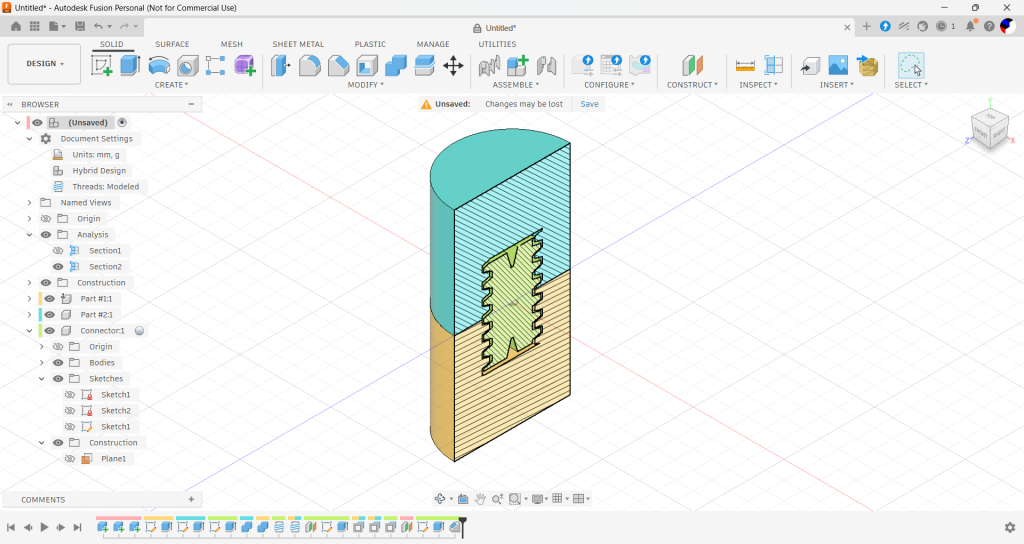
What now?
That’s up to you! Explore how to use these 3D printed threads for fastening, moving mechanisms or just for looks! Personally I’m going to do all of the above as I put these to work for my engineering and cosplay projects: there’s one project in particular I will revisit soon…
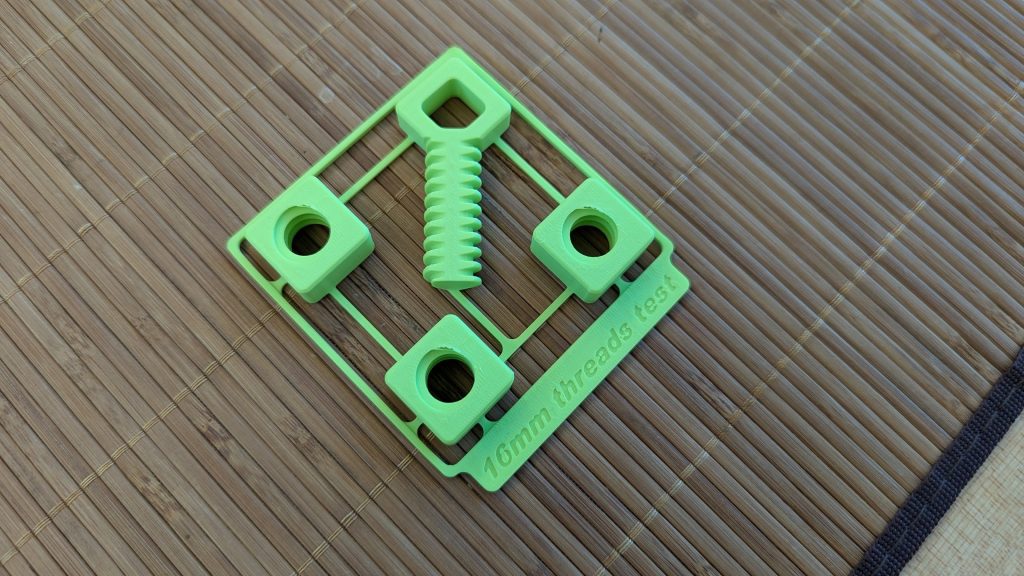
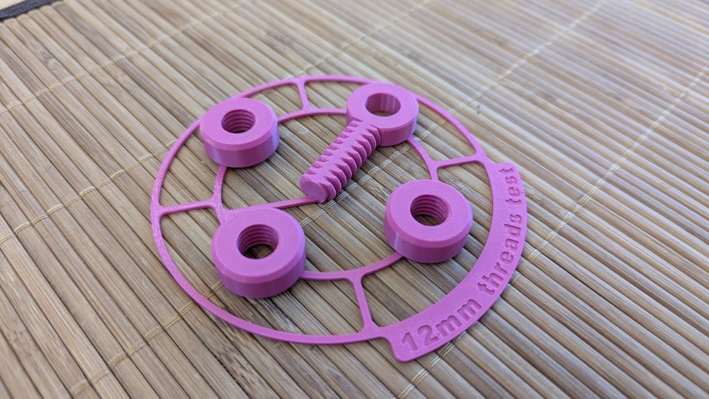
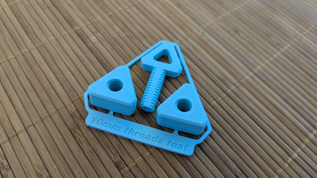
Remember to download the charms I designed and try them out ! I dug into my inner kawaii/gachapon/otaku for these: let me know what you think, good luck with your prints and above everything else have fun!
Would you like to know more?
Like I said at the top, some problems with 3D printed threads had already been figured out: they just needed someone to put them together. Here’s some of the resources I found online that helped me learn more about 3D printing threads as I was gearing up to this chunk of research!
The article “Threads and screws: 3D print them perfectly every time” at my All3DP (did you know I used to write there?) was a great refresher on the general state of 3D modeling and 3D printing threads.
Hackaday has covered so many ways to 3D print threads that they just have a printed threads tag now. It was great inspiration for using my newly designed threads in ways I hadn’t thought of yet!
The Snapmaker blog has a “Guide to designing and 3D printing threads” with some great suggestions on printing settings (especially bumping up solidity with additional perimeters). Other suggestions like adding chamfers didn’t work for me, but overall it’s a good read!